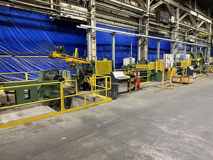
16” (405mm) x .008”-.039” (0.2mm – 1.0mm) Automatic High-Speed High-Precision Slitting Line (Used)
No longer available
Specifications
| Condition | Used |
| Stock Number | VX-1725 |
Description
General Specifications:
Gauge Range: .008”-.039” (0.2mm ~1mm)
Width Capacity: 7.87” – 16” (200mm – 405mm)
Inner diameter of coils: Φ (16”, 20”) (406mm, 508mm.)
Outer diameter of coils: max Φ 47” (1200mm.)
Max. coil weight: 9,920.8 Lbs. (4500Kg)
Line Direction: Left to Right