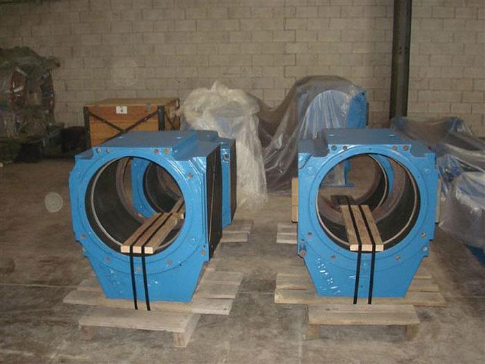
32´´ SENDZIMIR COLD REVERSING MILL (USED)

Specifications
| Model | ZR-67-32 |
| Condition | Used |
| Stock Number | VX-17350 |
| Mill builder | Mull Industries, Inc. |
| Z-high type | ZR 67-30, Inter. Roll Driven |
| Minimum | Blue Book Number Plus 20% |
| Maximum | To Be Determined |
| Extreme maximum for single pass | 0.135" |
| Maximum entry | 0.115" |
| Nominal entry gauge | 0.080" |
| Minimum entry | 0.012" |
| Maximum finish | 0.080" |
| Minimum finish | 0.006" |
| Clearance circle diameter | 82" |
| Coil weight | 14,000 Lb. Maximum, 438 PIW |
| Maximum diameter | 3.50" |
| Nominal diameter | 3.15" |
| Minimum diameter | 2.80" |
| Roll face | 38" (approximate) |
| Lateral adjustment range | 4½" |
| Side support roll bearing diameter | 2.362" |
| Driven rolls | Upper & Lower Z-High Intermediate Rolls |
| Mill drive | 1500 HP @ 0/600/900 RPM (1, Mill Motor Mill Duty |
| Mill drive torque | 150 HP/100 FPM |
| Mill speed range | 0/967/1451 FPM |
Description
Material Specifications: Material Rolled: - Aluminum - All Grades Yield Strength Range: Minimum: 11,000 psi, Maximum: 45,000 psi Tensile Strength Range: Strip Width: Minimum 16", Maximum: 32" Strip Thickness: Coil Size: I.D.: 20", O.D.: 72" (With Paper L.H. Winder) Coil Build Up Ratio: 3.6:1 (Based on 72" O.D.) Z-High Operation - Mill Section: ZR 67-32 Work Roll: Intermediate Roll Diameter: Maximum Diameter: 7.7" Nominal Diameter: 7.35" Minimum Diameter: 7.0" Side Support Roll: Maximum Diameter: 3.00" Nominal Diameter: 2.88" Minimum Diameter: 2.76" Back Up Roll Diameter: Roll Face: 37.5" Maximum Diameter: 29" Nominal Diameter: 27.875" Minimum Diameter: 26.75" Overloads of 1.15 cont., 1.25 for 2 hours Pinion Stand Ratio 1.25:1 Maximum Roll Separating Force: 512,000 Lbs. at Maximum Screwdown Cylinder Pressure Pinion Stand Ratio: 1.25:1 Note: Anticipated forward slip will be up to 10%, or 0/1000/1500 FPM strip speed for forward slip greater than or equal to 3.3% Work Rolls: Standard design work roll axially located by thrust bearings mounted on front and rear work roll doors. Upper Work Roll can be supported during threading by Work Roll Lifters which are hydraulically operated. Side Support Rolls: Each work roll is supported by two side support rolls - one on the entry side and one on the delivery side. These rolls are fitted with anti-friction bearings housed in chocks located in the cluster arm. Side Support Cluster Arm Assemblies: Each side support roll is backed up by two rows of bearings called side support bearings mounted on fixed shafts. These shafts in turn are mounted within the cluster arms which themselves are each supported on a pivot shaft. The pivot shafts span from the drive side intermediate roll chock to the operator's side immediate roll chock. Each Cluster arm is designed to be pushed by hydraulic cylinder for pre-loading of the insert. Intermediate Rolls: The two intermediate rolls are located, one each, between work roll and the back-up rolls. These rolls are also of alloy forged steel fitted with anti-friction bearings without inner race and supported in intermediate roll chocks. Drive to these rolls is given from the mill motor via a gear reducer / pinion stand and the drive spindles. Lubrication to the Intermediate Roll Chock bearings is by oil mist. Lateral Adjustment Range: 4-1/2" Intermediate Roll Bending: Full roll bending, "crown in" and "crown out" is provided by double acting cylinders located between the upper and lower intermediate roll chocks. These cylinders also serve as counter balance of the upper intermediate roll assembly. Lateral Adjustment of Intermediate Rolls: The drives for the axial adjustment of the intermediate rolls are effected by means of hydraulic cylinders. Mill shape can be adjusted by adjustment of the taper relief's at opposite ends of the intermediate rolls. Lateral Adjustment housings using dual cylinders connected to a cross bar arrangement to deliver lateral force to the Intermediate Roll - Operator's Side - Upper and Lower. The dual cylinder design provides for a compact design in order to minimize the overhung load on the Intermediate Roll Chocks. Work Roll Doors: Work Roll Thrust Doors, located at the front and rear of the mill, contain the work roll thrust bearings. The front door is unlatched and opened manually in order to insert and remove the work rolls from the mill. It is only necessary to open the back door when the rear thrust bearings need to be replaced. Note: The front Work Roll thrust bearing must be removed when the insert is being changed out. Mae West Blocks: These blocks are mounted at pass line height to the window face of each of the four housing posts. Recesses are provided in the housing post liners to accept the blocks. These blocks perform the following functions: They incorporate the balance cylinders for the upper back-up roll. They provide horizontal (lateral) support for the intermediate roll chocks, and mounting faces for the intermediate roll chock keeper plates. They provide a mounting surface for the work roll thrust door hinges and latches. They provide mounting surface for the intermediate roll change actuator and rails. Side Support Beams: These beams are permanently mounted to the Mae West blocks between the operator's side and the drive. The Side Support beams can be moved in and out (with respect to the vertical centerline of the mill) to accommodate the grind down range of the rolls. The Side Support Beams are thus positioned using vertically driven wedges which are positioned and synchronized by mechanically linked Duff-Norton jacks. Line Currently In Storage


